
Hydraulic Motors
![]()
![]()
![]()
![]()
![]()
![]()
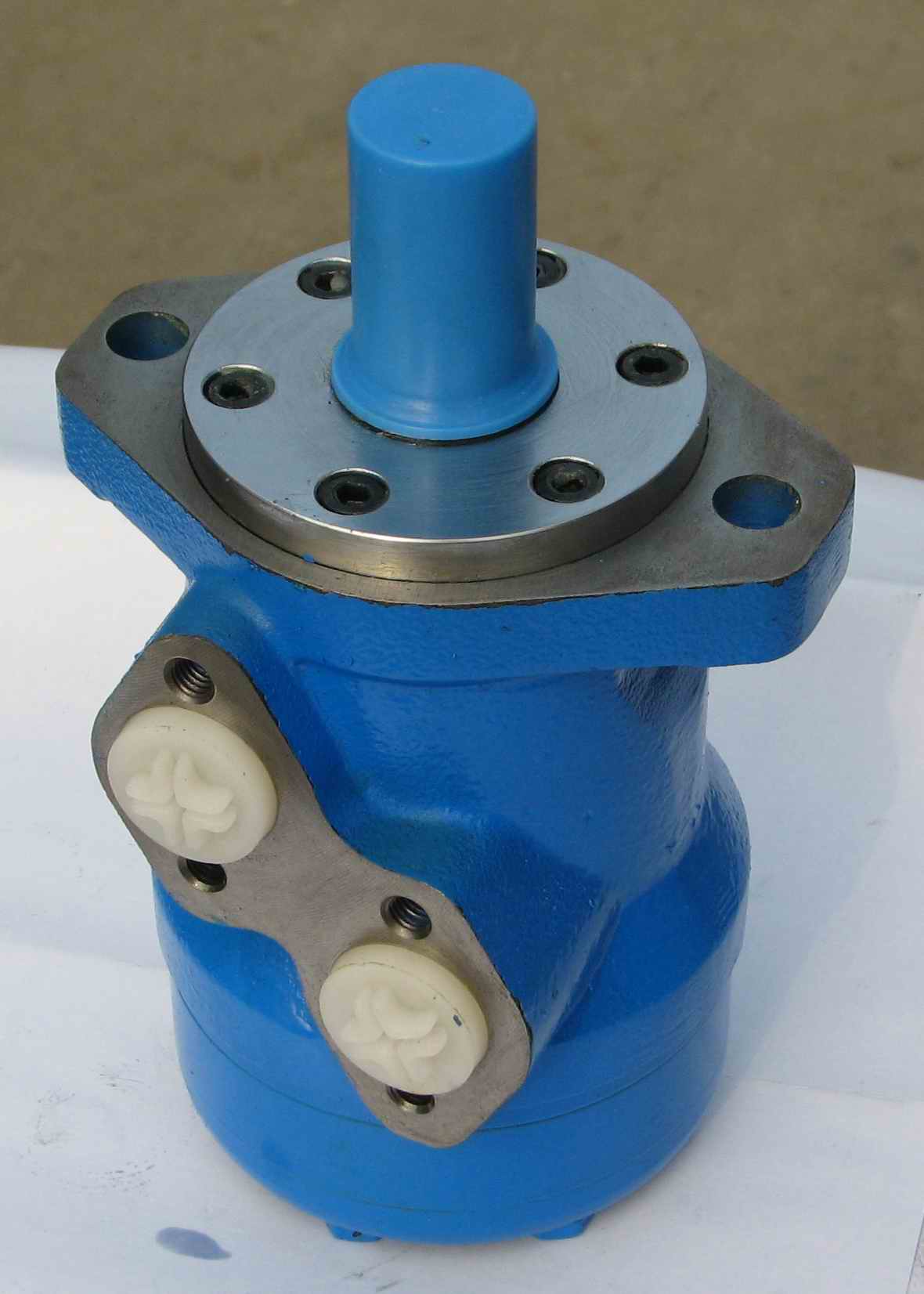
BMT Series Hydraulic Motor
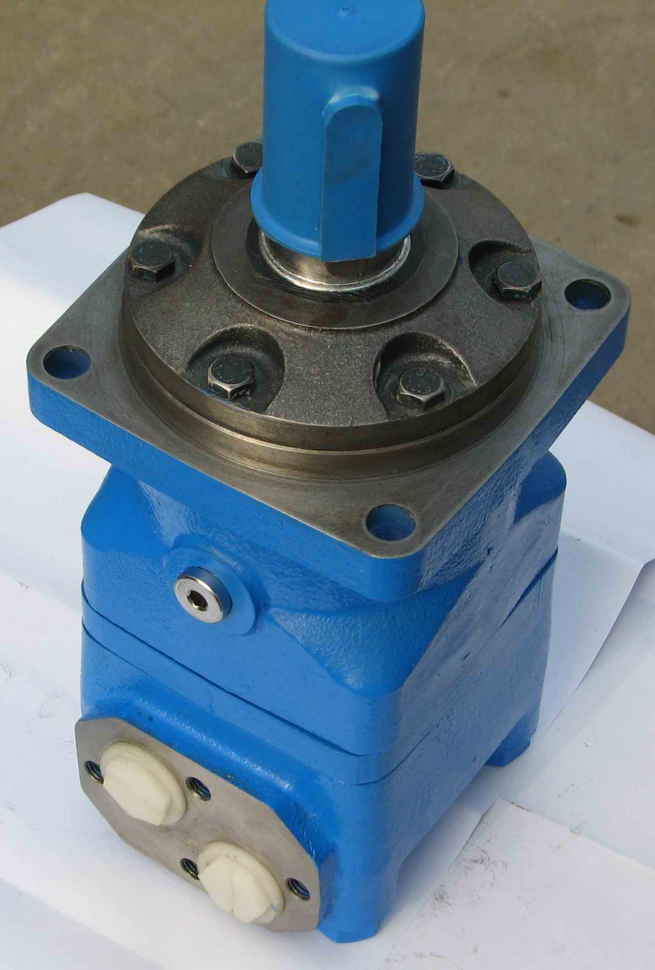
BMT series motor adapt the advanced Gerotor gear set design with disc distribution flow and high pressure. The unit can be supplied the individual variant in operating multifunction in accordance with requirement of applications.
Characteristic Features:
*Advanced manufacturing devices for the Gerotor gear set, which use low pressure of start-up, provide smooth and reliable operation and high efficiency.
*The output shaft adapts in tapered roller bearings that permit high axial and radial forces. Can offer capacities of high pressure and high torque in the wide of applications.
*Advanced design in disc distribution flow, which can automatically compensate in operating with high volume efficiency and long life, provide smooth and reliable operation.
Order Code:
BMT | — | 囗 | — | 囗 | — | 囗 | — | 囗 | — | 囗 | — | 囗 | — | 囗 |
① | ② | ③ | ④ | ⑤ | ⑥ | ⑦ | ⑧ |
BMTS | — | 囗 | — | 囗 | — | 囗 | — | 囗 | — | 囗 | — | 囗 | — | 囗 |
① | ② | ③ | ④ | ⑤ | ⑥ | ⑦ | ⑧ |
| ① Code | Remarks | |
| BMT BMTS | ||
| ② Displacement | ||
| 160 200 250 315 400 500 630 800 | ||
| ③ Flange | ||
| 4 | 4-Ø14 Square-flangeØ160,pilotØ125×9 | BMT |
| K6 | 4-Ø14.5Square-flangeØ162,pilotØ127×9 | |
| W | 4-Ø18 Wheel-flangeØ200,pilotØ160×7 | |
| D | 4-Ø14 Circle-flange Ø160,pilot Ø125×8 | BMTS |
| E | 4-Ø14.5 Square-flange Ø162, pilot Ø127×10 | |
| ④ Output Shaft | ||
| M | Shaft Ø40,parallel key 12×8×70 | BMT |
| G | Shaft Ø38.1,parallel key 9.52×9.52×57.15 | |
| F | Shaft Ø38.1,splined tooth 17-DP12/24 | |
| FD | Shaft Ø38.1,splined tooth 17-DP12/24 | |
| T | Cone-shaft 1:10 Ø45,parallel key B12×8×28 | |
| T1 | Cone-shaft 1:8 Ø45,parallel key 11.13×11.13×31.75 | |
| SL | shaft Ø34.85,Splined key,Splined key 6-34.85×28.14×8.64 | |
| G1 | shaftØ31.75,parallel key 7.96×7.96×40 | |
| F1 | Shaft Ø31.75,splined tooth 14-DP12/24 | |
| Omit | Short shaft 16-DP12/24 | BMTS |
| ⑤ Port and Drain Port | ||
| D | G3/4 Manifold Mount,4-M10 , G1/4 | |
| M | M27×2 Manifold Mount,4-M10, M14×1.5 | |
| S | 1-1/16-12UN O-ring, 9/16-18UNF | |
| S1 | 1-1/16-12UN O-ring, 7/16-20UNF | |
| G | G3/4,G1/4 | |
| M3 | M27×2,M14×1.5 | |
| ⑥ Rotation Direction | ||
| Omit | Standard | |
| R | Opposite | |
| ⑦ Paint | ||
| 00 | No paint | |
| Omit | Blue | |
| B | Black | |
| S | Silver grey | |
| ⑧ Unusually Function | ||
| Omit | Standard | |
| LL | Low Leakage | |
| F | Free Running | |
| LS | Low Speed | |
BMTE | — | 囗 | — | 囗 | — | 囗 | — | 囗 | — | 囗 | — | 囗 | — | 囗 |
① | ② | ③ | ④ | ⑤ | ⑥ | ⑦ | ⑧ |
BMTJ | — | 囗 | — | 囗 | — | 囗 | — | 囗 | — | 囗 | — | 囗 | — | 囗 |
① | ② | ③ | ④ | ⑤ | ⑥ | ⑦ | ⑧ |
| ① Code | Remarks | |
| BMTE BMTJ | ||
| ② Displacement | ||
| 230 250 315 400 500 630 800 | ||
| ③ Flange | ||
| CC | 4-Ø14.3 Square-flange Ø161.9,pilot Ø127×12 | BMTE |
| WE | 4-1/2-13UNC Wheel-flangeØ147.6,pilot Ø127×9 | |
| J | 4-Ø14.5 Square-flange Ø161.9,pilot Ø127×12.4 | BMTJ |
| ④ Output Shaft | ||
| G2 | Shaft Ø38.1,parallel key 9.52×9.52×42 | BMTE |
| FE | Shaft Ø38.1,splined tooth 17-DP12/24 | |
| Y1 | Shaft Ø40,parallel key 12×8×63 | |
| Y2 | Shaft Ø40,parallel key 12×8×63 | |
| T2 | Cone-shaft 1:8 Ø41.25,parallel key 11.13×11.13×31.75 | |
| T3 | Cone-shaft 1:8 Ø41.25,parallel key 11.13×11.13×31.75 | |
| Omit | Short shaft 12-DP8.5/17 | BMTJ |
| ⑤ Port and Drain Port | ||
| SF | 3/4”, Manifold Mount,8-3/8-16UNC, 7/16-20UNF | |
| SF5 | 1-5/16-12UN O-ring,7/16-20 UNF | |
| SF6 | M33×2,M14×1.5 | |
| SF7 | G1,G1/4 | |
| SE | 1-1/16-12UN O-ring,9/16-18 UNF | |
| SE1 | 1-1/16-12UN O-ring,7/16-20 UNF | |
| SE2 | G3/4,G1/4 | |
| ⑥ Rotation Direction | ||
| Omit | Standard | |
| R | Opposite | |
| ⑦ Paint | ||
| 00 | No paint | |
| Omit | Blue | |
| B | Black | |
| S | Silver grey | |
| ⑧ Unusually Function | ||
| Omit | Standard | |
| LL | Low Leakage | |
| F | Free Running | |
| LS | Low Speed | |
Main Specifications:
| Type | BMT 160 | BMT 200 | BMT 230 | BMT 250 | BMT 315 | BMT 400 | BMT 500 | BMT 630 | BMT 800 | |
| Geometric displacement (cm3 /rev.) | 161.1 | 201.4 | 232.5 | 251.8 | 326.3 | 410.9 | 523.6 | 629.1 | 801.8 | |
| Max. speed (rpm) | cont. | 625 | 625 | 536 | 500 | 380 | 305 | 240 | 196 | 154 |
| int. | 780 | 750 | 643 | 600 | 460 | 365 | 285 | 233 | 185 | |
| Max. torque (N·m) | cont. | 470 | 590 | 670 | 730 | 950 | 1080 | 1220 | 1318 | 1464 |
| int. | 560 | 710 | 821 | 880 | 1140 | 1260 | 1370 | 1498 | 1520 | |
| peak | 669 | 838 | 958 | 1036 | 1346.3 | 1450.3 | 1643.8 | 1618.8 | 1665 | |
| Max. output (kW) | cont. | 27.7 | 34.9 | 34.7 | 34.5 | 34.9 | 31.2 | 28.8 | 25.3 | 22.2 |
| int. | 32 | 40 | 40 | 40 | 40 | 35 | 35 | 27.5 | 26.8 | |
| Max. pressure drop (MPa) | cont. | 20 | 20 | 20 | 20 | 20 | 18 | 16 | 14 | 12.5 |
| int. | 24 | 24 | 24 | 24 | 24 | 21 | 18 | 16 | 13 | |
| peak | 28 | 28 | 28 | 28 | 28 | 24 | 21 | 19 | 16 | |
| Max. flow (L/min) | cont. | 100 | 125 | 125 | 125 | 125 | 125 | 125 | 125 | 125 |
| int. | 125 | 150 | 150 | 150 | 150 | 150 | 150 | 150 | 150 | |
| Max. inlet pressure (MPa) | cont. | 21 | 21 | 21 | 21 | 21 | 21 | 21 | 21 | 21 |
| int. | 25 | 25 | 25 | 25 | 25 | 25 | 25 | 25 | 25 | |
| peak | 30 | 30 | 30 | 30 | 30 | 30 | 30 | 30 | 30 | |
| Weight (kg) | 19.5 | 20 | 20.4 | 20.5 | 21 | 22 | 23 | 24 | 25 | |
* Intermittent pressure :Max. value of operating motor in 6 seconds per minute.
* Peak pressure:Max. value of operating motor in 0.6 second per minute.
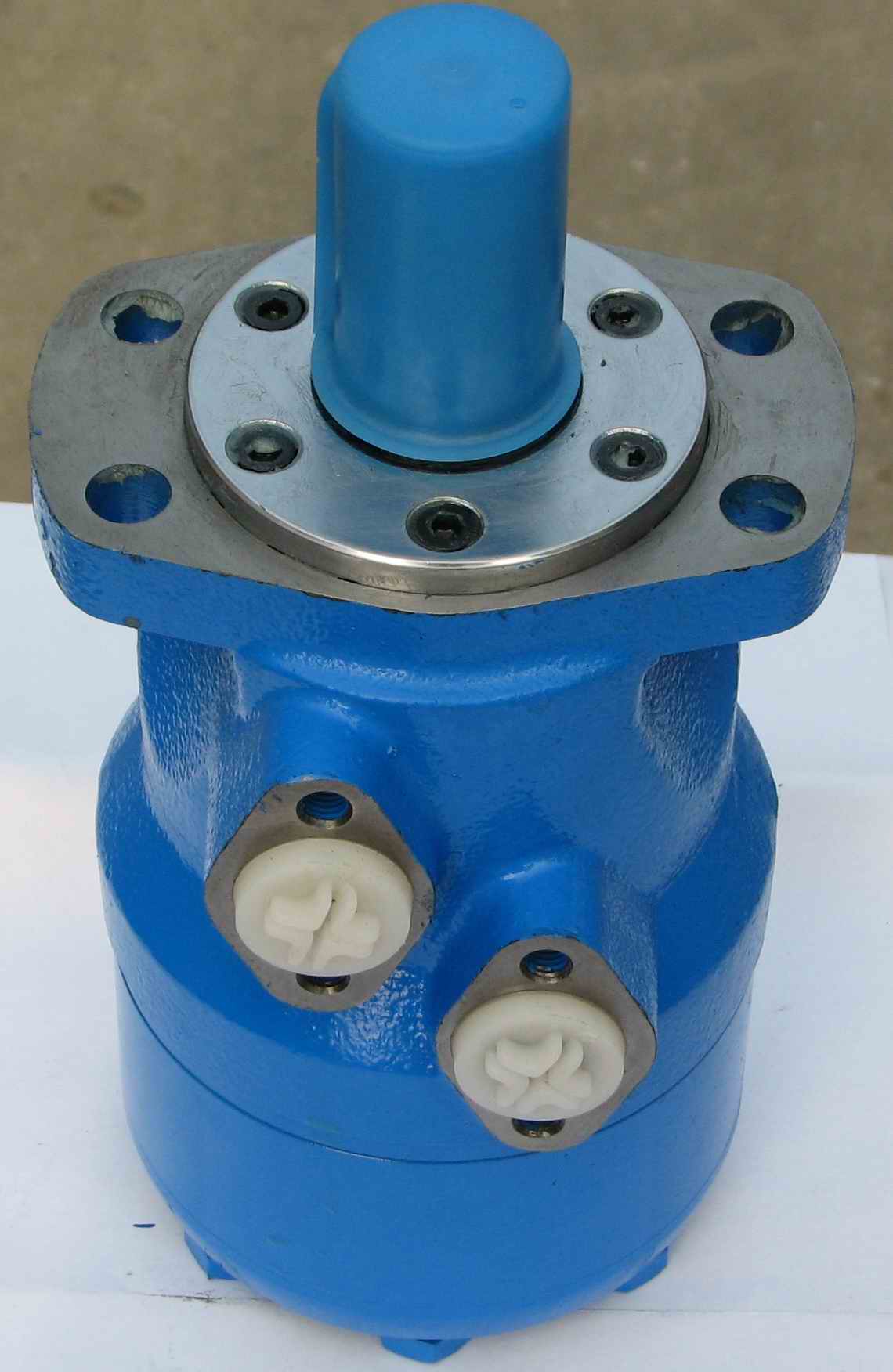
BMS Series Hydraulic Motor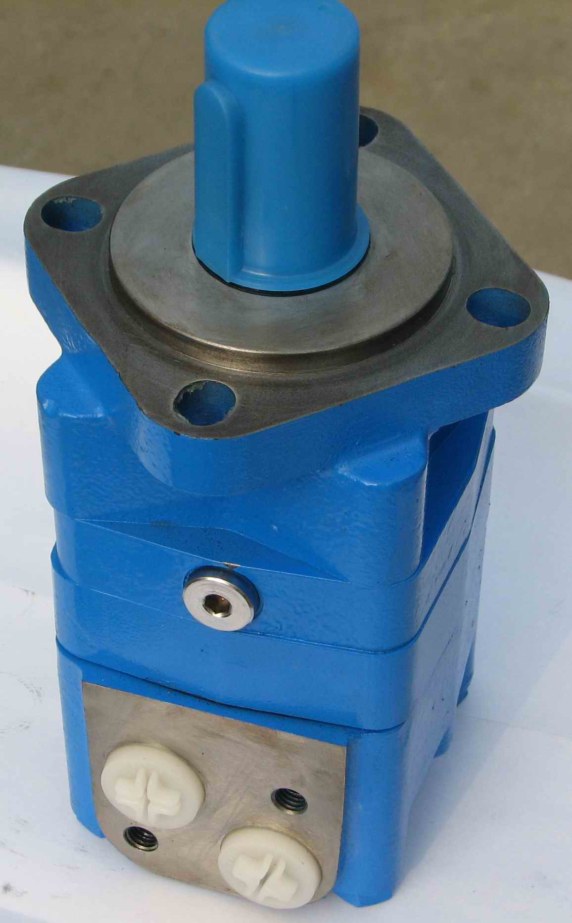
BMS series motor adapt the advanced Gerotor gear set design with disc distribution flow and high pressure. The unit can be supplied the individual variant in operating multifunction in accordance with requirement of applications.
Characteristic Features:
*Advanced manufacturing devices for the Gerotor gear set which use low pressure of start-up, provide smooth and reliable operation and high efficiency.
*The output shaft adapts in tapered roller bearings that permit high axial and radial forces. Can offer capacities of high pressure and high torque in the wide of applications.
*Advanced design in disc distribution flow, which can automatically compensate in operating with high volume efficiency and long life, provide smooth and reliable operation.
Order Code:
BMS | — | 囗 | — | 囗 | — | 囗 | — | 囗 | — | 囗 | — | 囗 | — | 囗 |
① | ② | ③ | ④ | ⑤ | ⑥ | ⑦ | ⑧ |
BMSS | — | 囗 | — | 囗 | — | 囗 | — | 囗 | — | 囗 | — | 囗 | — | 囗 |
① | ② | ③ | ④ | ⑤ | ⑥ | ⑦ | ⑧ |
| ① Code | Remarks | |
| BMS BMSS | ||
| ② Displacement | ||
| 80 100 125 160 200 250 315 375 | ||
| ③ Flange | ||
| E2 | 2-Ø13.5 Rhomb-flange Ø106.4,pilot Ø82.5×6.3 | BMS |
| E4 | 4-Ø13.5 Rhomb-flange Ø106.4,pilot Ø82.5×6.3 | |
| F6 | 6-Ø13.5 Rhomb-flange Ø106.4,pilot Ø82.5×2.6 | |
| W | 4-Ø13.5 Wheel-flange Ø160,pilot Ø125×8 | |
| E2B | 2-Ø14.3 Rhomb-flange Ø146.05,pilot Ø101.6×9.4 | |
| SP | 4-Ø11.5 Square-flange Ø106.4,pilot Ø82.5×6.3 | |
| D | 4-Ø11 Circle-flange Ø125,pilot Ø100×6 | BMSS |
| E | 4-Ø13.5 Square-flange Ø127,pilot Ø101.6×6.3 | |
| ④ Output Shaft | ||
| A | Shaft Ø25 , parallel key 8×7×32 | BMS |
| B | Shaft Ø32 , parallel key 10×8×45 | |
| D | Shaft Ø25.4 , parallel key6.35×6.35×25.4 | |
| G | Shaft Ø31.75,parallel key 7.96×7.96×31.75 | |
| F | Shaft Ø31.75,splined tooth 14-DP12/24 | |
| FD | Long Shaft Ø31.75,splined tooth 14-DP12/24 | |
| SL | shaft Ø34.85,Splined key 6-34.85×28.14×8.64 | |
| T1 | Cone-shaft Ø35 ,parallel key B6×6×20 | |
| T3 | Cone-shaftØ31.75,parallel key 7.96×7.96×31.75 | |
| S1 | Shaft Ø25.4 ,splined tooth SAE 6B | |
| I | Sub-shaft Ø22,splined tooth 13-DP16/32 | |
| Omit | Short shaft 12-DP12/24 | BMSS |
| ⑤ Port and Drain Port | ||
| D | G1/2 Manifold Mount 2-M10 , G1/4 | |
| M | M22×1.5 Manifold Mount 2-M10, M14×1.5 | |
| S | 7/8-14UNF O-ring manifold 2-3/8-16, 7/16-20UNF | |
| P | 1/2-14NPTF manifold 2-3/8-16UNC, 7/16-20UNF | |
| ⑥ Rotation Direction | ||
| Omit | Standard | |
| R | Opposite | |
| ⑦ Paint | ||
| 00 | No paint | |
| Omit | Blue | |
| B | Black | |
| S | Silver grey | |
| ⑧ Unusually Function | ||
| Omit | Standard | |
| LL | Low Leakage | |
| F | Free Running | |
| LS | Low Speed | |
BMSE | — | 囗 | — | 囗 | — | 囗 | — | 囗 | — | 囗 | — | 囗 | — | 囗 |
① | ② | ③ | ④ | ⑤ | ⑥ | ⑦ | ⑧ |
BMSJ | — | 囗 | — | 囗 | — | 囗 | — | 囗 | — | 囗 | — | 囗 | — | 囗 |
① | ② | ③ | ④ | ⑤ | ⑥ | ⑦ | ⑧ |
| ① Code | Remarks | |
| BMSE BMSJ | ||
| ② Displacement | ||
| 80 100 125 160 200 250 315 375 | ||
| ③ Flange | ||
| E2 | 2-Ø13.5 Rhomb-flange Ø106.4,pilot Ø82.5×6.3 | BMSE |
| E4 | 4-Ø13.5 Rhomb-flange Ø106.4,pilot Ø82.5×6.3 | |
| E2B | 2-Ø14.3 Rhomb-flange Ø146.05,pilot Ø101.6×9.4 | |
| E6 | 4-Ø13.5 Rhomb-flange Ø106.4,pilot Ø82.5×6.3 | |
| WE | 4-Ø13.6Wheel-flangeØ147.6,pilot Ø107.95*6.4 | |
| J | 4-Ø13.5 Square-flange Ø127,pilot Ø101.6×6.3 | BMSJ |
| ④ Output Shaft | ||
| A | Shaft Ø25 , parallel key 8×7×32 | BMSE |
| B | Shaft Ø32 , parallel key 10×8×45 | |
| K | Shaft Ø25.4 , Woodruff key Ø25.4×6.35 | |
| G | Shaft Ø31.75, parallel key 7.96×7.96×31.75 | |
| F | Shaft Ø31.75 , splined tooth 14-DP12/24 | |
| T4 | Cone-shaft Ø31.75 , parallel key 7.96×7.96×25.4 | |
| S1 | Shaft Ø25.4 ,splined tooth SAE 6B | |
| I | Sub-shaft Ø22 , splined tooth 13-DP16/32 | |
| Omit | Short shaft12- DP12/24 | BMSJ |
| ⑤ Port and Drain Port | ||
| MU | 1/2”,5/8”Crosshole Manifold 3×3/8-16UNC,7/16-20UNF | |
| MM | 1/2”,5/8”Crosshole Manifold 3×M10,G1/4 | |
| EE-D | G1/2,G1/4 | |
| EE-M2 | M22×1.5,M14×1.5 | |
| EE-S2 | 7/8-14UNF O-ring,7/16-20 UNF | |
| ED | 1-1/16-12UN O-ring,7/16-20 UNF | |
| DB | G1/2,G1/4 | |
| DU | G1/2,7/16-20 UNF | |
| SB | 7/8-14UNF O-ring,G1/4 | |
| SU | 7/8-14UNF O-ring,7/16-20 UNF | |
| M4 | M22×1.5,M14×1.5 | |
| ⑥ Rotation Direction | ||
| Omit | Standard | |
| R | Opposite | |
| ⑦ Paint | ||
| 00 | No paint | |
| Omit | Blue | |
| B | Black | |
| S | Silver grey | |
| ⑧ Unusually Function | ||
| Omit | Standard | |
| LL | Low Leakage | |
| F | Free Running | |
| LS | Low Speed | |
Main Specifications:
| Type | BMS BMSE 80 | BMS BMSE 100 | BMS BMSE 125 | BMS BMSE 160 | BMS BMSE 200 | BMS BMSE 250 | BMS BMSE 315 | BMS BMSE 375 | |
| Geometric displacement (cm3 /rev.) | 80.6 | 100.8 | 125 | 157.2 | 200 | 252 | 314.5 | 370 | |
| Max. speed (rpm) | cont. | 800 | 748 | 600 | 470 | 375 | 300 | 240 | 200 |
| int. | 988 | 900 | 720 | 560 | 450 | 360 | 280 | 240 | |
| Max. torque (N·m) | cont. | 190 | 240 | 310 | 316 | 400 | 450 | 560 | 536 |
| int. | 240 | 300 | 370 | 430 | 466 | 540 | 658 | 645 | |
| peak | 260 | 320 | 400 | 472 | 650 | 690 | 740 | 751 | |
| Max. output (kW) | cont. | 15.9 | 18.8 | 19.5 | 15.6 | 15.7 | 14.1 | 14.1 | 11.8 |
| int. | 20.1 | 23.5 | 23.2 | 21.2 | 18.3 | 17 | 18.9 | 17 | |
| Max. pressure drop (MPa) | cont. | 17.5 | 17.5 | 17.5 | 15 | 14 | 12.5 | 12 | 10 |
| int. | 21 | 21 | 21 | 21 | 16 | 16 | 14 | 12 | |
| peak | 22.5 | 22.5 | 22.5 | 22.5 | 22.5 | 20 | 18.5 | 14 | |
| Max. flow (L/min) | cont. | 65 | 75 | 75 | 75 | 75 | 75 | 75 | 75 |
| int. | 80 | 90 | 90 | 90 | 90 | 90 | 90 | 90 | |
| Max. inlet pressure (MPa) | cont. | 25 | 25 | 25 | 25 | 25 | 25 | 25 | 25 |
| int. | 30 | 30 | 30 | 30 | 30 | 30 | 30 | 30 | |
| Weight (kg) | 9.8 | 10 | 10.3 | 10.7 | 11.1 | 11.6 | 12.3 | 12.6 | |
* Intermittent pressure :Max. value of operating motor in 6 seconds per minute.
* Peak pressure:Max. value of operating motor in 0.6 second per minute.
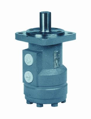
BMR Series Hydraulic Motor
BMR series motor adapt the advanced Gerolor gear set design with shaft distribution flow, which can automatically compensate in operating with high pressure , provide reliable and smooth operation, high efficiency and long life.
Characteristic Features:
*Advanced manufacturing devices for the Gerolor gear set, which use low pressure of start-up, provide smooth, reliable operation and high efficiency.
*Shaft seal can bear high pressure of back and the motor can be used in parallel or in series.
*Special design in the driver-linker and prolong operating life
*Special design for distribution system can meet the requirement of low noise of unit.
*Compact volume and easy installation.
Order Code:
BMR | — | 囗 | — | 囗 | — | 囗 | — | 囗 | — | 囗 | — | 囗 | — | 囗 |
① | ② | ③ | ④ | ⑤ | ⑥ | ⑦ | ⑧ |
| ① Code | |
| BMR | |
| ② Displacement | |
| 36 50 80 100 125 160 200 250 315 375 | |
| ③ Flange | |
| 2 | 2-Ø13.5 Rhomb-flange,pilot Ø82.5×8 |
| 4 | 4-Ø13.5 Rhomb-flange,pilot Ø82.5×8 |
| H4 | 4-3/8-16 Square-flange,pilot Ø44.4×2.8 |
| H5 | 4-M10 Square-flange,pilot Ø44.4×2.8 |
| ④ Output Shaft | |
| A | Shaft Ø25,parallel Key 8x7x32 |
| B | Shaft Ø32,parallel Key 10x8x45 |
| C | Shaft Ø25.4,parallel Key 6.35x6.35x31.75 |
| E | Shaft Ø25.4,splined tooth SAE 6B |
| R | Short shaft Ø25.4,parallel key 6.35x6.35x31.75 |
| F | Shaft Ø31.75,splined tooth 14-DP12/24 |
| FD | Long shaft Ø31.75,splined tooth 14-DP12/24 |
| G | Shaft Ø31.75,parallel Key 7.96x7.96x31.75 |
| T | Cone-Shaft Ø28.56,parallel Key B5x5x14 |
| ⑤ Port and Drain Port | |
| D | G1/2 Manifold Mount 4-M8, G1/4 |
| M | M22×1.5 Manifold Mount 4-M8, M14×1.5 |
| S | 7/8-14 O-ring manifold 4-5/16-18UNC, 7/16-20UNF |
| P | 1/2-14 NPTF Manifold 4-5/16-18UNC,7/16-20UNF |
| R | PT(Rc)1/2 Manifold 4-M8, PT(Rc)1/4 |
| ⑥ Rotation Direction | |
| Omit | Standard |
| R | Opposite |
| ⑦ Paint | |
| 00 | No paint |
| Omit | Blue |
| B | Black |
| S | Silver grey |
| ⑧ Unusually Function | |
| Omit | Standard |
| N | Big radial force |
| O | No case drain |
| F | Free Running |
| LS | Low Speed |
BMRS | — | 囗 | — | 囗 | — | 囗 | — | 囗 | — | 囗 | — | 囗 | — | 囗 |
① | ② | ③ | ④ | ⑤ | ⑥ | ⑦ | ⑧ |
| ① Code | |
| BMRS | |
| ② Displacement | |
| 36 50 80 100 125 160 200 250 315 375 | |
| ③ Flange | |
| H2 | 2-Ø13.5 Rhomb-flange, pilot Ø82.5×2.8 |
| H6 | 4-Ø13.5 Rhomb-flange, pilot Ø82.5×2.8 |
| H4 | 4-3/8-16 Square-flange, pilot Ø44.4×2.8 |
| H5 | 4-M10 Square-flange, pilot Ø44.4×2.8 |
| ④ Output Shaft | |
| K | Shaft Ø25.4,Woodruff Key Ø25.4×6.35 |
| S | Sub-shaft Ø25.4,splined tooth SAE 6B |
| A | Shaft Ø25 , parallel key 8×7×32 |
| R | Shaft Ø25.4, parallel key 6.35×6.35×31.75 |
| H | Sub-shaft Ø25.4,Pin hole Ø10.3 |
| H1 | Shaft Ø25.4, pin hole Ø8 |
| D | Shaft Ø22.22, parallel key 6.35×6.35×25.4 |
| I | Shaft Ø22.22, splined tooth13-DP16/32 |
| T2 | Cone shaft Ø25.4 , woodruff key Ø25.4×6.35 |
| P | Shaft Ø25,parallel Key 8×7×28 |
| J | Shaft Ø25,parallel Key 7×7×32 |
| ⑤ Port and Drain Port | |
| G | G1/2, G1/4 |
| S | 7/8-14 O-ring 7/16-20UNF (G1/4) |
| P | 1/2-14 NPTF, 7/16-20UNF (G1/4) |
| T | 3/4-16 O-ring, 7/16-20UNF |
| R | PT(Rc)1/2, PT(Rc)1/4 |
| B4 | Ø10 O-ring manifold 4x5/16-18, 7/16-20UNF |
| B5 | Ø10 O-ring manifold 4xM8, G1/4 |
| M1 | M18×1.5, M10×1 |
| M2 | M20×1.5, M10×1 |
| M3 | M22×1.5, M10×1 |
| ⑥ Rotation Direction | |
| Omit | Standard |
| R | Opposite |
| ⑦ Paint | |
| 00 | No paint |
| Omit | Blue |
| B | Black |
| S | Silver grey |
| ⑧ Unusually Function | |
| Omit | Standard |
| N | Big radial force |
| O | No case drain |
| F | Free Running |
| LS | Low Speed |
Main Specifications:
Technical data for BMR with 25 and 1 in and 1 in splined and 28.56 tapered shaft:
| Type | BMR BMRS 36 | BMR BMRS 50 | BMR BMRS 80 | BMR BMRS 100 | BMR BMRS 125 | BMR BMRS 160 | BMR BMRS 200 | BMR BMRS 250 | BMR BMRS 315 | BMR BMRS 375 | |
| Geometric displacement (cm3 /rev.) | 36 | 51.7 | 81.5 | 102 | 127.2 | 157.2 | 194.5 | 253.3 | 317.5 | 381.4 | |
| Max. speed (rpm) | cont. | 1085 | 960 | 750 | 600 | 475 | 378 | 310 | 240 | 190 | 155 |
| int. | 1220 | 1150 | 940 | 750 | 600 | 475 | 385 | 300 | 240 | 190 | |
| Max. torque (N·m) | cont. | 72 | 100 | 195 | 240 | 300 | 360 | 360 | 390 | 390 | 365 |
| int. | 83 | 126 | 220 | 280 | 340 | 430 | 440 | 490 | 535 | 495 | |
| peak | 105 | 165 | 270 | 320 | 370 | 460 | 560 | 640 | 650 | 680 | |
| Max. output (kW) | cont. | 8.5 | 9.5 | 12.5 | 13 | 12.5 | 12.5 | 10 | 7 | 6 | 5 |
| int. | 9.8 | 11.2 | 15 | 15 | 14.5 | 14 | 13 | 9.5 | 9 | 8 | |
| Max. pressure drop (MPa) | cont. | 14 | 14 | 17.5 | 17.5 | 17.5 | 16.5 | 13 | 11 | 9 | 7 |
| int. | 16.5 | 17.5 | 20 | 20 | 20 | 20 | 17.5 | 15 | 13 | 10 | |
| peak | 22.5 | 22.5 | 22.5 | 22.5 | 22.5 | 22.5 | 22.5 | 20 | 17.5 | 15 | |
| Max. flow (L/min) | cont. | 40 | 50 | 60 | 60 | 60 | 60 | 60 | 60 | 60 | 60 |
| int. | 45 | 60 | 75 | 75 | 75 | 75 | 75 | 75 | 75 | 75 | |
| Weight (kg) | 6.5 | 6.7 | 6.9 | 7 | 7.3 | 7.6 | 8 | 8.5 | 9 | 9.5 | |
| Type | BMR BMRS 36 | BMR BMRS 50 | BMR BMRS 80 | BMR BMRS 100 | BMR BMRS 125 | BMR BMRS 160 | BMR BMRS 200 | BMR BMRS 250 | BMR BMRS 315 | BMR BMRS 375 | |
| Geometric displacement (cm3 /rev.) | 36 | 51.7 | 81.5 | 102 | 127.2 | 157.2 | 194.5 | 253.3 | 317.5 | 381.4 | |
| Max. speed (rpm) | cont. | 1250 | 960 | 750 | 600 | 475 | 378 | 310 | 240 | 190 | 155 |
| int. | 1520 | 1150 | 940 | 750 | 600 | 475 | 385 | 300 | 240 | 190 | |
| Max. torque (N·m) | cont. | 72 | 100 | 195 | 240 | 300 | 380 | 450 | 540 | 550 | 580 |
| int. | 83 | 126 | 220 | 280 | 340 | 430 | 500 | 610 | 690 | 690 | |
| peak | 105 | 165 | 270 | 320 | 370 | 460 | 560 | 710 | 840 | 830 | |
| Max. output (kW) | cont. | 8.5 | 9.5 | 12.5 | 13 | 12.5 | 12.5 | 11 | 10 | 9 | 7.5 |
| int. | 9.8 | 11.2 | 15 | 15 | 14.5 | 14 | 13 | 12 | 10 | 9 | |
| Max. pressure drop (MPa) | cont. | 14 | 14 | 17.5 | 17.5 | 17.5 | 17.5 | 17.5 | 17.5 | 13.5 | 11.5 |
| int. | 16.5 | 17.5 | 20 | 20 | 20 | 20 | 20 | 20 | 17.5 | 15 | |
| peak | 22.5 | 22.5 | 22.5 | 22.5 | 22.5 | 22.5 | 22.5 | 22.5 | 21 | 17.5 | |
| Max. flow (L/min) | cont. | 45 | 50 | 60 | 60 | 60 | 60 | 60 | 60 | 60 | 60 |
| int. | 55 | 60 | 75 | 75 | 75 | 75 | 75 | 75 | 75 | 75 | |
| Weight (kg) | 6.5 | 6.7 | 6.9 | 7 | 7.3 | 7.6 | 8 | 8.5 | 9 | 9.5 | |
* Intermittent pressure :Max. value of operating motor in 6 seconds per minute.
* Peak pressure:Max. value of operating motor in 0.6 second per minute.
BM2, BM3 Series Hydraulic Motor
BBM2, BM3 series motor adapt shaft distribution flow design with a radial ball bearing and can provide longer life in this distrbution system of which separated the output shaft from system.
Characteristic Features:
* Separated off output shaft, the distribution system not bear any of load force, only carry distribution flow effect, rotating in coordinate with housing no friction, provide low leakage, high volume efficiency and long life.
* Can bear the Max. radial load force, which adapt dual bearing design.
* Advanced the Gerotor gear set design, provide high mechanical efficiency and reliable operation.
* Shaft seal can bear high pressure of back and motor can be used in parallel or series.
* Advanced construction design, provide high power and low weight.
Main Specifications:
| Type | BM2 100 | BM2 125 | BM2 160 | BM2 200 | BM2 250 | BM2 315 | BM2 400 | BM3 500 | BM3 600 | |
| Geometric displacement (cm3 /rev.) | 100 | 124.1 | 164.7 | 200 | 248.3 | 319.2 | 400 | 518 | 666 | |
| Max. speed (rpm) | rated | 400 | 400 | 310 | 250 | 200 | 150 | 125 | 160 | 125 |
| int. | 500 | 500 | 400 | 310 | 250 | 200 | 150 | 200 | 160 | |
| Max. torque (N·m) | rated | 198 | 215 | 285 | 347 | 385 | 495 | 477 | 772 | 993 |
| int. | 241 | 268 | 355 | 459 | 470 | 568 | 620 | 1054 | 1355 | |
| Max. output (kW) | rated | 8.1 | 8.8 | 9 | 9 | 8 | 8 | 6 | 13 | 13 |
| int. | 9.6 | 11 | 11 | 11 | 10 | 9 | 9 | 17 | 17 | |
| Max. pressure drop (MPa) | rated | 16 | 14 | 14 | 14 | 12.5 | 12.5 | 10 | 12.5 | 12.5 |
| int. | 19 | 17 | 17 | 17 | 14 | 14 | 12.5 | 16 | 16 | |
| Max. inlet pressure (MPa) | rated | 20 | 20 | 20 | 20 | 20 | 20 | 20 | 20 | 20 |
| int. | 25 | 25 | 25 | 25 | 25 | 25 | 25 | 25 | 25 | |
| Weight (kg) | 6.7 | 7.2 | 7.8 | 8.1 | 8.4 | 9.0 | 9.5 | 17.5 | 18.5 | |
BMP Series Hydraulic Motor
BMP series motor are small volume, economical type, which is designed with shaft distribution flow, which adapt the Gerotor gear set design and provide compact volume, high power and low weigth.
Characteristic Features:
* Advanced manufacturing devices for the Gerotor gear set, which provide small volume, high efficiency and long life.
* Shaft seal can bear high pressure of motor of which can be used in parallel or series.
* Advanced construction design, high power and low weight.
Order Code:
BMP | — | 囗 | — | 囗 | — | 囗 | — | 囗 | — | 囗 | — | 囗 | — | 囗 |
① | ② | ③ | ④ | ⑤ | ⑥ | ⑦ | ⑧ |
| ① Code | |
| BMP | |
| ② Displacement | |
| 36 50 80 100 125 160 200 250 315 400 500 | |
| ③ Flange | |
| 2 | 2-Ø13.5 Rhomb-flange,pilot Ø82.5×8 |
| 4 | 4-Ø13.5 Rhomb-flange,pilot Ø82.5×8 |
| H4 | 4-3/8-16 Square-flange,pilot Ø44.4×2.8 |
| H5 | 4-M10 Square-flange,pilot Ø44.4×2.8 |
| ④ Output Shaft | |
| A | Shaft Ø25,parallel Key 8x7x32 |
| B | Shaft Ø32,parallel Key 10x8x45 |
| C | Shaft Ø25.4,parallel Key 6.35x6.35x31.75 |
| E | Shaft Ø25.4,splined tooth SAE 6B |
| R | Short shaft Ø25.4,parallel key 6.35x6.35x31.75 |
| F | Shaft Ø31.75,splined tooth 14-DP12/24 |
| FD | Long shaft Ø31.75,splined tooth 14-DP12/24 |
| G | Shaft Ø31.75,parallel Key 7.96x7.96x31.75 |
| T | Cone-Shaft Ø28.56,parallel Key B5x5x14 |
| T3 | Cone shaft Ø31.75,parallel key 7.96x7.96x25.4 |
| ⑤ Port and Drain Port | |
| D | G1/2 Manifold Mount 4xM8, G1/4 |
| M | M22×1.5 Manifold Mount 4xM8, M14×1.5 |
| S | 7/8-14 O-ring manifold 4x5/16-18UNC, 7/16-20UNF |
| P | 1/2-14 NPTF Manifold 4x5/16-18UNC,7/16-20UNF |
| R | PT(Rc)1/2 Manifold 4xM8, PT(Rc)1/4 |
| ⑥ Rotation Direction | |
| Omit | Standard |
| R | Opposite |
| ⑦ Paint | |
| 00 | No paint |
| Omit | Blue |
| B | Black |
| S | Silver grey |
| ⑧ Unusually Function | |
| Omit | Standard |
| N | Big radial force |
| O | No case drain |
| F | Free Running |
| LS | Low Speed |
BMPH | — | 囗 | — | 囗 | — | 囗 | — | 囗 | — | 囗 | — | 囗 | — | 囗 |
① | ② | ③ | ④ | ⑤ | ⑥ | ⑦ | ⑧ |
| ① Code | |
| BMPH | |
| ② Displacement | |
| 36 50 80 100 125 160 200 250 315 400 500 | |
| ③ Flange | |
| H2 | 2-Ø13.5 Rhomb-flange,pilot Ø82.5×2.8 |
| H6 | 4-Ø13.5 Rhomb-flange,pilot Ø82.5×2.8 |
| H4 | 4-3/8-16 Square-flange,pilot Ø44.4×2.8 |
| H5 | 4-M10 Square-flange,pilot Ø44.4×2.8 |
| ④ Output Shaft | |
| K | Shaft Ø25.4, woodruff key Ø25.4×6.35 |
| S | Shaft Ø25.4, splined tooth SEA 6B |
| A | Shaft Ø25, parallel key 8×7×32 |
| R | Shaft Ø25.4, parallel key 6.35×6.35×31.75 |
| H | Shaft Ø25.4, pin hole Ø10.3 |
| H1 | Shaft Ø25.4, pin hole Ø8 |
| D | Shaft Ø22.22, parallel key 6.35×6.35×25.4 |
| I | Shaft Ø22.22, splined tooth 13-DP16/32 |
| T2 | Cone shaft Ø25.4, woodruff key Ø25.4×6.35 |
| P | Shaft Ø25,parallel key 8×7×28 |
| J | Shaft Ø25,parallel key 7×7×32 |
| ⑤ Port and Drain Port | |
| G | G1/2, G1/4 |
| S | 7/8-14 O-ring ,7/16-20UNF |
| P | 1/2-14 NPTF, 7/16-20UNF |
| T | 3/4-16 O-ring, 7/16-20UNF |
| R | PT(Rc)1/2 ,PT(Rc)1/4 |
| B4 | Ø10 O-ring manifold 4x5/16-18UNC,7/16-20UNF |
| B5 | Ø10 O-ring manifold 4xM8,7/16-20UNF |
| ⑥ Rotation Direction | |
| Omit | Standard |
| R | Opposite |
| ⑦ Paint | |
| 00 | No paint |
| Omit | Blue |
| B | Black |
| S | Silver grey |
| ⑧ Unusually Function | |
| Omit | Standard |
| N | Big radial force |
| O | No case drain |
| F | Free Running |
| LS | Low Speed |
BMPW | — | 囗 | — | 囗 | — | 囗 | — | 囗 | — | 囗 | — | 囗 | — | 囗 |
① | ② | ③ | ④ | ⑤ | ⑥ | ⑦ | ⑧ |
| ① Code | |
| BMPW | |
| ② Displacement | |
| 50 80 100 125 160 200 250 315 400 500 | |
| ③ Flange | |
| Omit | Wheel-flange pilot Ø80×7.5 |
| ④ Output Shaft | |
| A | Shaft Ø25k6 ,Parallel key 8×7×32 |
| C | Shaft Ø25.4 ,Parallel key 6.35×6.35×31.75 |
| E | Shaft Ø25.4 ,Splined key SAE 6B |
| T | Cone shaft Ø28.56 ,Parallel key B5×5×14 |
| ⑤ Port and Drain Port | |
| G | G1/2, G1/4 |
| S | 7/8-14 O-ring, 7/16-20UNF |
| W | M22×1.5,M14×1.5 |
| ⑥ Rotation Direction | |
| Omit | Standard |
| R | Opposite |
| ⑦ Paint | |
| 00 | No paint |
| Omit | Blue |
| B | Black |
| S | Silver grey |
| ⑧ Unusually Function | |
| Omit | Standard |
| N | Big radial force |
| O | No case drain |
Main Specifications:
| Type | BMP BMPH BMPW 36 | BMP BMPH BMPW 50 | BMP BMPH BMPW 80 | BMP BMPH BMPW 100 | BMP BMPH BMPW 125 | BMP BMPH BMPW 160 | BMP BMPH BMPW 200 | BMP BMPH BMPW 250 | BMP BMPH BMPW 315 | BMP BMPH BMPW 400 | BMP BMPH BMPW 500 | |
| Geometric displacement (cm3 /rev.) | 36 | 51.7 | 77.7 | 96.2 | 120.2 | 157.2 | 194.5 | 240.3 | 314.5 | 389.5 | 486.5 | |
| Max. speed (rpm) | cont. | 1500 | 1150 | 770 | 615 | 490 | 383 | 310 | 250 | 192 | 155 | 120 |
| int. | 1650 | 1450 | 960 | 770 | 615 | 475 | 385 | 310 | 240 | 190 | 150 | |
| Max. torque (N·m) | cont. | 55 | 100 | 146 | 182 | 236 | 302 | 360 | 380 | 375 | 360 | 385 |
| int. | 76 | 128 | 186 | 227 | 290 | 370 | 440 | 460 | 555 | 525 | 560 | |
| peak | 96 | 148 | 218 | 264 | 360 | 434 | 540 | 550 | 650 | 680 | 680 | |
| Max. output (kW) | cont. | 8 | 10 | 10 | 11 | 10 | 10 | 10 | 8.5 | 7 | 6 | 5 |
| int. | 11.5 | 12 | 12 | 13 | 12 | 12 | 12 | 10.5 | 8.5 | 7 | 6 | |
| Max. pressure drop (MPa) | cont. | 12.5 | 14 | 14 | 14 | 14 | 14 | 14 | 11 | 9 | 7 | 6 |
| int. | 16.5 | 17.5 | 17.5 | 17.5 | 17.5 | 17.5 | 17.5 | 14 | 14 | 10.5 | 9 | |
| peak | 22.5 | 22.5 | 22.5 | 22.5 | 22.5 | 22.5 | 22.5 | 18 | 16 | 14 | 12 | |
| Max. flow (L/min) | cont. | 55 | 60 | 60 | 60 | 60 | 60 | 60 | 60 | 60 | 60 | 60 |
| int. | 60 | 75 | 75 | 75 | 75 | 75 | 75 | 75 | 75 | 75 | 75 | |
| Weight (kg) | 5.6 | 5.6 | 5.7 | 5.9 | 6 | 6.2 | 6.4 | 7 | 6.9 | 7.4 | 8 | |
| Type | BMP BMPH 36 | BMP BMPH 50 | BMP BMPH 80 | BMP BMPH 100 | BMP BMPH 125 | BMP BMPH 160 | BMP BMPH 200 | BMP BMPH 250 | BMP BMPH 315 | BMP BMPH 400 | BMP BMPH 500 | |
| Geometric displacement (cm3 /rev.) | 36 | 51.7 | 77.7 | 96.2 | 120.2 | 157.2 | 194.5 | 240.3 | 314.5 | 389.5 | 486.5 | |
| Max. speed (rpm) | cont. | 1500 | 1150 | 770 | 615 | 490 | 383 | 310 | 250 | 192 | 155 | 120 |
| int. | 1650 | 1450 | 960 | 770 | 615 | 475 | 385 | 310 | 240 | 190 | 150 | |
| Max. torque (N·m) | cont. | 55 | 100 | 146 | 182 | 236 | 302 | 360 | 460 | 475 | 490 | 430 |
| int. | 76 | 128 | 186 | 227 | 290 | 370 | 440 | 570 | 555 | 580 | 560 | |
| peak | 96 | 148 | 218 | 264 | 360 | 434 | 540 | 670 | 840 | 840 | 780 | |
| Max. output (kW) | cont. | 8 | 10 | 10 | 11 | 10 | 10 | 10 | 8.5 | 7 | 6 | 6 |
| int. | 11.5 | 12 | 12 | 13 | 12 | 12 | 12 | 10.5 | 8.5 | 7 | 7 | |
| Max. pressure drop (MPa) | cont. | 12.5 | 14 | 14 | 14 | 14 | 14 | 14 | 14 | 12 | 9.5 | 7 |
| int. | 16.5 | 17.5 | 17.5 | 17.5 | 17.5 | 17.5 | 17.5 | 17.5 | 14 | 11.5 | 9 | |
| peak | 22.5 | 22.5 | 22.5 | 22.5 | 22.5 | 22.5 | 22.5 | 22.5 | 22.5 | 18 | 13 | |
| Max. flow (L/min) | cont. | 55 | 60 | 60 | 60 | 60 | 60 | 60 | 60 | 60 | 60 | 60 |
| int. | 60 | 75 | 75 | 75 | 75 | 75 | 75 | 75 | 75 | 75 | 75 | |
| Weight (kg) | 5.6 | 6 | 5.7 | 5.9 | 6 | 6.2 | 6.4 | 7 | 6.9 | 7.4 | 8 | |
* Intermittent pressure :Max. value of operating motor in 6 seconds per minute.
* Peak pressure:Max. value of operating motor in 0.6 second per minute.
BMV Series Hydraulic Motor
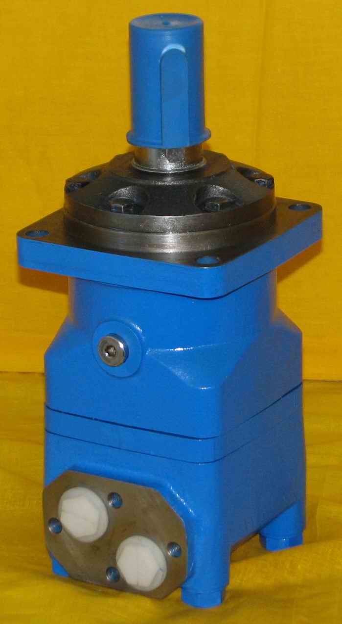
BMV series motor adapt the advanced Gerotor gear set, design with disc distribution flow and high pressure. The unit can be supplied theindividual variant in operating multifunction in accordance with requirement of applications.
Characteristic Features:
*Advanced manufacturing devices for the Gerotor gear set, which use low pressure of start-up, provide smooth and reliable operationand high efficiency.
*The output shaft adapts in tapered roller bearings that permit high axial and radial forces. Can offer capacities of high pressure and hightorque in the wide of applications.
*Advanced design in disc distrbution flow, which can automatically compensate in operating with high volume efficiency and long life,provide smooth and reliable operation
Order Code:
BMV | — | 囗 | — | 囗 | — | 囗 | — | 囗 | — | 囗 | — | 囗 | — | 囗 |
① | ② | ③ | ④ | ⑤ | ⑥ | ⑦ | ⑧ |
| ① Code | |
| BMV | |
| ② Displacement | |
| 315 400 500 630 800 1000 | |
| ③ Flange | |
| 4 | 4-Ø18 Square-flangeØ200,pilot Ø160×11 |
| W | 4-Ø18 Wheel-flange Ø224,pilot Ø180×10 |
| ④ Output Shaft | |
| A | Shaft Ø50 , parallel key 14×9×70 |
| BD | Shaft Ø53.975, splined key 16-DP8/16 |
| B | Shaft Ø53.975, splined key 16-DP8/16 |
| C | Shaft Ø57.15, parallel key 12.7×12.7×57.15 |
| T | Cone shaft Ø60, parallel key B16×10×32 |
| T1 | Cone shaft Ø60, parallel key 14.308×14.308×50.8 |
| ⑤ Port and Drain Port | |
| D | G1 Manifold 4×M12, G1/4 |
| M | M33×2 Manifold 4×M12, M14×1.5 |
| S | 1-5/16-12UN, 9/16-18UNFG1, |
| G | G1/4 |
| M5 | M33×2, M14×1.5 |
| S1 | 1-5/16-12UN(18),7/16-20UNF(12) |
| ⑥ Rotation Direction | |
| Omit | Standard |
| R | Opposite |
| ⑦ Paint | |
| 00 | No paint |
| Omit | Blue |
| B | Black |
| S | Silver grey |
| ⑧ Unusually Function | |
| Omit | Standard |
Main Specifications:
| Type | BMV 315 | BMV 400 | BMV 500 | BMV 630 | BMV 800 | BMV 1000 | |
| Geometric displacement (cm3 /rev.) | 333 | 419 | 518 | 666 | 801 | 990 | |
| Max. speed (rpm) | cont. | 510 | 500 | 400 | 320 | 250 | 200 |
| int. | 630 | 600 | 480 | 380 | 300 | 240 | |
| Max. torque (N·m) | cont. | 920 | 1180 | 1460 | 1660 | 1880 | 2015 |
| int. | 1110 | 1410 | 1760 | 1940 | 2110 | 2280 | |
| peak | 1290 | 1640 | 2050 | 2210 | 2470 | 2400 | |
| Max. output (kW) | cont. | 38 | 47 | 47 | 40 | 33 | 28.6 |
| int. | 46 | 56 | 56 | 56 | 44 | 40 | |
| Max. pressure drop (MPa) | cont. | 20 | 20 | 20 | 18 | 16 | 14 |
| int. | 24 | 24 | 24 | 21 | 18 | 16 | |
| peak | 28 | 28 | 28 | 24 | 21 | 18 | |
| Max. flow (L/min) | cont. | 160 | 200 | 200 | 200 | 200 | 200 |
| int. | 200 | 240 | 240 | 240 | 240 | 240 | |
| Weight (kg) | 31.8 | 32.6 | 33.5 | 34.9 | 36.5 | 38.6 | |
* Intermittent pressure :Max. value of operating motor in 6 seconds per minute.
* Peak pressure:Max. value of operating motor in 0.6 second per minute.